Physics, Engineering and Computer Science
The School of Physics, Engineering and Computer Science is home to some of the UK’s best teaching facilities. We offer a stimulating and inclusive learning community which prepares our graduates for careers with top organisations. Our graduates have worked for NASA, Ferrari, Amazon and Morgan Stanley to name just a few! We truly are a multidisciplinary School, and we welcome you to join us.
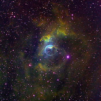
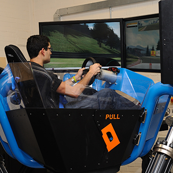
Our School has excellent undergraduate laboratories. You’ll benefit from world-class learning and experiential facilities to develop the practical skills you’ll need for your dream career. Our Bayfordbury Observatory is regarded as one of the best astronomical teaching observatories in the country. Our students get hands-on experience with our range of optical, radio and solar telescopes. Our flight simulators, supersonic wind tunnels and driving simulators help our engineers of the future bring theory to life. While our specialist artificial intelligence and robotics labs, inspire the design and development of the next generation of robotics. You can be certain that wherever your passion lies, in the School of Physics, Engineering and Computer Science, we’ve got the facilities to help you excel.
You’ll be taught by exceptional academics from across the STEM spectrum . Our renowned research influences our teaching. Every step of the way, you’ll learn about the latest advancements in your specialist area. This includes our internationally recognised research into the astrophysics of galaxies and black holes, quantum computing and climate change. Plus, our research on green energy, energy harvesting, biodetection and protection of people, plants and animals. Meanwhile our research in computer science is advancing biocomputation and algorithm research.
You’ll benefit from our strong links to industry, in companies such as Airbus, Rolls Royce, Apple and Microsoft. With the option for a 1-year work placement, you can kickstart your career by working on innovative new projects with leading employers. At Herts, we’ll give you the opportunity to put your skills and knowledge to the test. The question is, what will you do with it?

Contact information
School of Physics, Engineering and Computer Science
University of Hertfordshire
Hatfield
Hertfordshire
AL10 9AB
UK
For subject enquiries please contact
Physics: Prof. Martin Hardcastle m.j.hardcastle@herts.ac.uk
Engineering: Mrs Susan Murray s.murray@herts.ac.uk
Computer Science: Dr Simon Trainis s.a.trainis@herts.ac.uk
+44 (0)1707 284394

